


Absolutely! Let’s dive into the world of the Knight Rider Circuit, a classic LED project that pays homage to the iconic scanning effect from the 1980s TV show. This Arduino-based project is not just fun, but also an excellent learning opportunity for beginners in electronics and programming.
Knight Rider Circuit: Recreating KITT’s Iconic Scanner
The Knight Rider Circuit replicates the famous red light sequence from the front of KITT, the AI-powered car in the 1980s TV show Knight Rider. It’s a fantastic way to learn Arduino programming while creating something visually impressive.
What You’ll Need:
Arduino UNO board
6 red LEDs
Breadboard
Jumper wires
Setting Up Your Circuit:
Hardware Assembly:
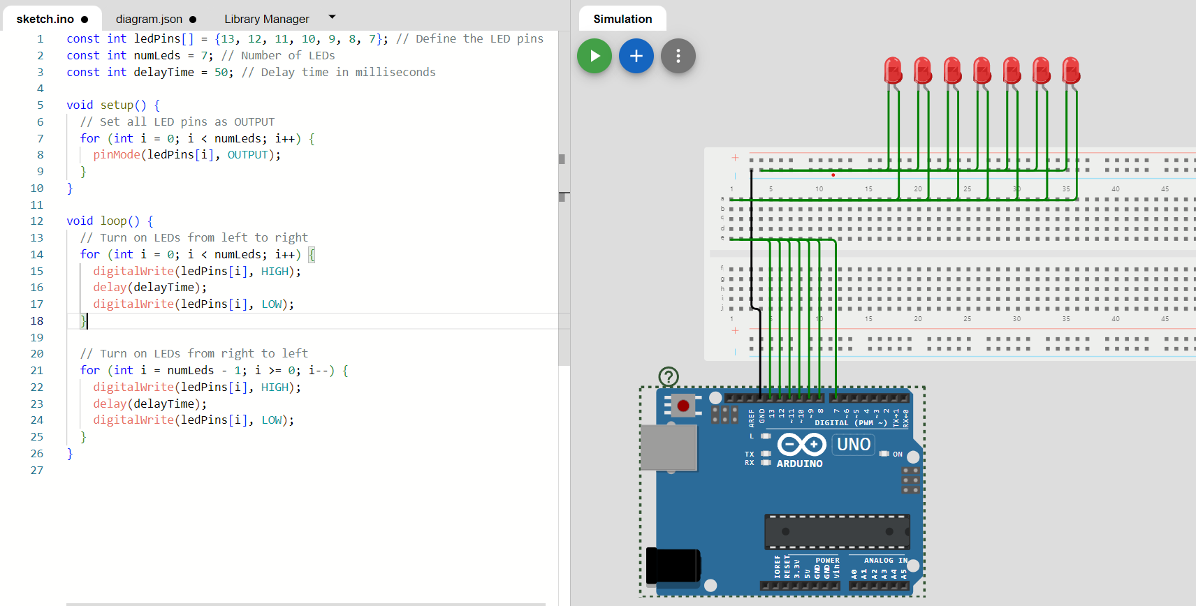
Arrange the LEDs in a row on your breadboard
Connect each LED’s long leg (anode) to Arduino pins 13, 12, 11, 10, 9, and 8
Link all LED short legs (cathodes) to the Arduino’s ground
Programming the Effect:
The Arduino sketch includes:
LED pin definitions: const int ledPins[] = {13, 12, 11, 10, 9, 8, 7};
A setup function to initialize pins
A loop function creating the scanning effect
How It Works:
The code creates the illusion of a moving light by sequentially activating LEDs:
Left-to-right scan: for (int i = 0; i < numLeds; i++)
Right-to-left scan: for (int i = numLeds – 1; i >= 0; i–)
Each LED lights up briefly (digitalWrite(ledPins[i], HIGH)), pauses, then turns off (digitalWrite(ledPins[i], LOW)).
Learning Opportunities:
Building a Knight Rider Circuit teaches you:
Arduino basics: pinMode, digitalWrite, delay
Programming concepts like loops and arrays
Breadboard prototyping skills
Simple LED control techniques
Enhancing Your Project:
Take your Knight Rider Circuit to the next level:
Add a potentiometer to adjust scanning speed
Create custom scanning patterns
Use RGB LEDs for multicolor effects
Sync sound effects with the light sequence
The Knight Rider Circuit is more than just a cool light show – it’s a gateway to the exciting world of electronics and programming. Whether you’re a beginner or looking for a fun project to teach others, this Arduino-based circuit offers a perfect mix of nostalgia and hands-on learning.
As you master this project, you’ll gain skills applicable to more complex Arduino challenges and custom LED designs. So channel your inner Michael Knight, power up that Arduino, and watch your very own KITT scanner come to life! Get ready to impress your friends and ignite your passion for DIY electronics with this classic Knight Rider effect.
Code is below.
const int ledPins[] = {13, 12, 11, 10, 9, 8, 7}; // Define the LED pins

const int numLeds = 7; // Number of LEDs

const int delayTime = 50; // Delay time in milliseconds

void setup() {

// Set all LED pins as OUTPUT

for (int i = 0; i < numLeds; i++) {

pinMode(ledPins[i], OUTPUT);

}

}

void loop() {

// Turn on LEDs from left to right

for (int i = 0; i < numLeds; i++) { digitalWrite(ledPins[i], HIGH); delay(delayTime); digitalWrite(ledPins[i], LOW); } // Turn on LEDs from right to left for (int i = numLeds - 1; i >= 0; i--) {

digitalWrite(ledPins[i], HIGH);

delay(delayTime);

digitalWrite(ledPins[i], LOW);

}

}